Oscillators generate a signal of a certain frequency.
Mixers can multiply two signals (bat signal with a local oscillator signal) to produce an audible difference tone.
Mixers
Multiplying two signals
The multiplication operation that is required to generate a signal of a frequency equal to the difference of the input frequencies, can be implemented in several ways.The intuitively easiest way is to use a special mixer IC, like the NE612 (or NE602) (pdf) or the MC1496 (pdf).
Actually a multiplied signal generally also appears when two signals are added and subsequently put through a non-linear device, like a pn-junction in a diode or transistor. Examples of this type of mixer are a transistor biased into non-linear operation, a simple two-diode mixer and more advanced four-diode balanced mixers.
 When using a square wave oscillator, the multiplication operation simply comes down to
reversing the polarity of the bat signal at the frequency of the local oscillator.
This can be implemented by using an analog switch to switch between the bat signal and an
inverted version of the bat signal.
When using a square wave oscillator, the multiplication operation simply comes down to
reversing the polarity of the bat signal at the frequency of the local oscillator.
This can be implemented by using an analog switch to switch between the bat signal and an
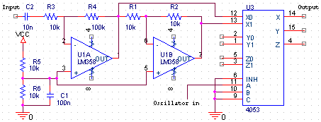
inverted version of the bat signal.In the picture on the right a basic implementation of this idea is shown. The leftmost opamp is configured as an inverting amplifier to give the signal some extra boost. The rightmost opamp is an inverting amplifier with gain -1. A 4053 is used to switch the output to either the output of opamp 1A or opamp 1B. The positive inputs of the opamps are biased at half the supply voltage.
Oscillators
Types of oscillators
Several types of oscillator exist, each with their own advantages and disadvantages.I know of the following types suitable for bat detectors:
- RC-type oscillators.
These can be built with a single opamp or a NE555 (pdf) for example. In these type of oscillators, the frequency is inversely proportional to the RC product. The nonlinear (inversely proportional) relationship between the RC product and the frequency is not very convenient. This can be alleviated somewhat by using a logarithmic potmeter, but in that case the clockwise position of the potmeter corrresponds to the lowest frequency. - LC-type oscillators.
These use a resonant LC-circuit to generate a relatively pure frequency (little harmonics). Disadvantages are the nonlinear relationship between LC and frequency and the lack of variable L or C with sufficient range (either L or C needs to be tuned in a 1:100 range to get frequencies between 10 kHz and 100 kHz). Using an LC-oscillator at high frequencies with the double heterodyne method solves both problems to some extent. - Voltage controlled oscillators.
These are generally special ICs where the output frequency depends on the input voltage. The VCO inside a 4046 PLL (pdf)is very convenient to use for example; it has a sufficient linear relationship between voltage and frequency and uses very little current, however it generates a square wave instead of the more desirable sine wave and it is sensitive to supply voltage.
Other examples are the MAX038 or ICL8038 function generator ICs. These can also generate sinewaves.
Stable triangle wave generator circuit
 A very nice circuit is shown on the right
(source: National Semiconductor, Application Note 31, February 1978,
Opamp circuit collection).
It outputs a triangle wave with a frequency essentially independent of supply voltage.
The triangle wave is already quite close to the ideal sine wave,
with the 3rd harmonic down by 19 dB.
A very nice circuit is shown on the right
(source: National Semiconductor, Application Note 31, February 1978,
Opamp circuit collection).
It outputs a triangle wave with a frequency essentially independent of supply voltage.
The triangle wave is already quite close to the ideal sine wave,
with the 3rd harmonic down by 19 dB.The opamp on the left is configured as a schmitt-trigger, whose treshold determines the triangle's amplitude. The opamp on the right is configured as an integrator, converting the square wave from the other opamp into a triangle.
To use this circuit with a single supply voltage, the grounded inputs on the opamps should be connected to half the supply voltage (by means of a resistive divider). For the opamps, a single TL072 dual-opamp IC can be used.
This page was last updated Sunday, June 25, 2000