The frequency is displayed on four 7-segment LED displays in xxx.x kHz format, with an estimated accuracy of better than 0.5% . Power consumption is low at approximately 7 mA at 6V.
4-digit frequency display
Introduction
This counter can be very useful in the determination of the bat call frequency. Just tune your heterodyne bat detector to the position where the bat call sounds lowest and read the frequency from the display. It also removes the need for a calibrated frequency scale, since you can simply read the frequency and adjust for the desired frequency. So there's no need anymore for an ultra-stable oscillator.The accuracy depends on the crystal connected to the microcontroller which can be very accurate.
Using LEDs for the display has the advantage that you can read the frequency when it is dark. This also means that the light level from the LEDs can be quite low and little supply current is used.
Hardware
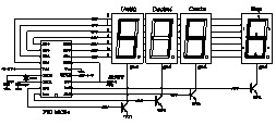
The frequency counter can be built using the popular PIC16C84 or PIC16F84 microcontrollers from Microchip. These are quite cheap to buy; development tools are freely downloadable and a simple programmer can be built out of about 10 electrical components. I don't have a schematic of the counter yet, but it is very similar to the
schematic on the right.
(link to original schematic)
Significant differences between this schematic and the schematic for my bat counter are:
I don't have a schematic of the counter yet, but it is very similar to the
schematic on the right.
(link to original schematic)
Significant differences between this schematic and the schematic for my bat counter are:- Forget about the transistors and the resistor connected to the transistors. They are not needed if you draw only a little current from the PIC. Connect RA0-RA3 directly to the respective common cathode connections of the LEDs.
- The resistor from RB1-RB7 to the 7-segment LED displays can be as large as 4.7 kohm, because the current through the LEDs can be very low.
- I'm using a clock crystal with built-in capacitors, which further reduces the number of components.
- The resistor that connects the input to RA4 is 10 kohm instead of 470 ohm.
The biggest problem with this circuit seems to be the crosstalk from the 100 Hz display refresh rate into the bat detector. This can be alleviated by placing sufficiently large capacitors across the supply. I think it's also good to keep the circuit as compact as possible.
Software
The microcontroller measures the frequency by counting the number of oscillator pulses in a 10 ms period. This value directly gives you the frequency in multiples of 100 Hz and can be put on the display. Counting the number of pulses is done with the built-in TMR0 counter and the prescaler, using a trick described in Microchip application note AN592.During counting, the display is also updated. Each digit is lighted for 2.5 ms by setting the appropiate common cathode pin (one of RA0-RA3) to 0 and outputting the a 7-segment code on the RB1-RB7 pins. Leading zeroes are removed so 43.5 kHz would indeed be displayed as 43.5 instead of 043.5, further saving average current consumption.
This is the PIC source code for use with a PIC16C84 and a common cathode display. You may need to make small changes to make it work with your particular type of processor and type of display. You can compile it into a .HEX file with the free MPASM compiler from Microchip.
Be sure to check that the source code compiles without errors. Especially the following things are important:
- Check if you use the PIC16C84 or the PIC16F84. There are a few small differences between the two processors You need to set a switch in the source-code to set the type. If you set this wrong, the microcontroller might not reset properly at start-up.
- Check if your display is of the common cathode or of the common anode type. Set the appropriate switch in the source code accordingly. The display probably looks very weird when you set this incorrectly.
- Make sure that you don't override the default radix of 10 by a commandline parameter. If you see 55x.x on the display instead of the frequency, then this is the problem.
Other counter stuff
2-digit counter
If you think that a frequency accuracy of 1 kHz and a frequency range of 0-99 kHz is still acceptable, then a display with only two digits is possible.It saves in cost and in current drain. Also the software for counting the pulses gets somewhat easier to program. Some experimental code for a two-digit counter can be found here.
Sorry, there's no nice picture of the hardware yet.
LED efficiency
The LED brightness for a given current can be increased by pulsing the LED at about 7 mA, instead of multiplexing it with 0.7 mA.LEDs are probably more efficient at a current of about 7 mA than at a current of 0.7 mA. Pulsing the LED at 7 mA with a 0.05 duty cycle results in the same average current as multiplexing it with 0.7 mA (considering a 2-digit display). However due to the higher efficiency, the brightness will be higher.
Suppose I want a 100 Hz update frequency and an average current of 0.35 mA, the following loop should do the trick:
- Count the number of pulses for 1000 microseconds (= 1 milisecond).
- Light the left digit for 500 microseconds
- Light the right digit for 500 microseconds.
- Dim both LEDs for 8000 microseconds to arrive at a total cycle period of 10 ms (=100 Hz)
I'm slightly worried about a possible increase in interference because of the higher currents.
Web links
Other plans involving frequency counters on the net:This page was last updated Tuesday, December 28, 1999