-
Introduction
The following are circuit ideas. There's no full, working circuit here yet.The microphone
The microphone needs to have a relatively flat frequency response. I think an electrostatic microphone, like the Polaroid transducer, will do well.A piezo-electric transducer, like I used in my first detector, is probably less useful. That type of microphone is only sensitive for sound in a very small region of frequencies around 40 kHz. My first detector used a division factor of 16, therefore virtually any ultrasonic noise sounded like a 2.5 kHz beep.
Pre-amplifier
Also needs to be relatively flat in frequency response, for the same reasons as given above. The bandwidth should be limited to minimise the noise. A frequency division detector already has a disadvantage (I estimate about 13 dB) over heterodyne detection because of its higher bandwidth that lets more noise in.The frequency converter
This is the interesting part.What an amplitude-retaining frequency division bat detector has to do, is obviously:
- divide the frequency
- retain the amplitude
I think there is a way of performing the division and the amplitude retention in a single step, and which will even give out a sine wave.
Dividing the frequency
 I'm thinking of using simply a comparator to square up the incoming signal and
then use it to drive a digital counter that controls an analog multiplexer.
For the comparator, a LM393 seems ideal, because it has low-power consumption and
still works well at low voltages.
I'm thinking of using simply a comparator to square up the incoming signal and
then use it to drive a digital counter that controls an analog multiplexer.
For the comparator, a LM393 seems ideal, because it has low-power consumption and
still works well at low voltages.The comparator can be cleverly designed to take advantage of the DC bias from the previous processsing stage (amplifier) and to react only on the AC part of the input waveform. The (-) input of the comparator sees the average value, because of the low-pass filter before the (-) input, while the (+) input of the comparator sees the raw unfiltered signal. This way, the comparator triggers only on the AC component of the input waveform. A little positive feedback from the output of the comparator to its (+) input makes sure that the comparator does not trigger on small noise signals.
 The squared-up signal is then fed into a digital counter, like the CMOS 4024 or 4040.
These ICs also have very low current consumption.
The squared-up signal is then fed into a digital counter, like the CMOS 4024 or 4040.
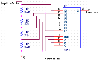
These ICs also have very low current consumption.The analog multiplexer connects its output to one of 8 voltages that form a sampled approximation of a sine wave, as shown on the right. Every pulse from the comparator will advance the multiplexer to the next voltage, so after 8 pulses, a full approximation has been made and a division by 8 has been accomplished at the same time.
Retaining the amplitude
 The amplitude can be retained by using a 'super-diode', which is a diode
in the feedback-loop of an opamp.
The opamp arrangement makes it seem as if the forward voltage drop of the diode is
drastically reduced.
The amplitude can be retained by using a 'super-diode', which is a diode
in the feedback-loop of an opamp.
The opamp arrangement makes it seem as if the forward voltage drop of the diode is
drastically reduced.The voltage at the output of the opamp (after low-pass filtering) is now related to the input amplitude. By feeding this amplitude signal into the sine-wave generator as described above, we have a retained amplitude frequency divided signal!
Headphone-amplifier
I'll use the trusty old LM386, together with some mild low-pass filtering to remove the residual harmonics (The 3rd and 5th harmonic that you would normally have with a simple square wave are already eliminated in this circuit).This page was last updated Monday, June 05, 2000